Activities
Schematic Capture with Fritzing
First stage for creating our circuit is to input the schematic, which describes which components we are going to use and how they are inter-connected.
Open fritzings 'Schematic' Tab.
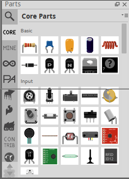
Select the parts from the 'Parts List' panel on the right hand side of the window, the left edge of this window is a column of icons, each one represents a category of components, select a category and it loads a page of components, drag the component onto the main window to add it to your circuit.
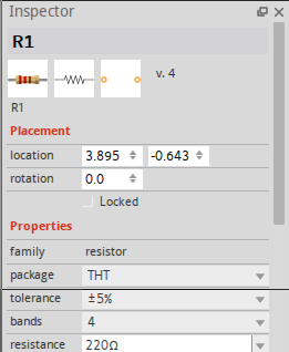
Each item has a number of options, such as the package type, or pin ordering. You can modify these by highlighting the component and the 'inspector' panel in the bottom right of the screen displays the various parameters and options for that component. Set these as per the chart.
| Category | Part | Options |
|---|---|---|
| Sparkfun Electromechanical | Battery Holder | Type: battcon_20mm_pth |
| Core | Pushbutton | |
| Core | resistor | 1k |
| Core | resistor | 10k |
| SparkFun-DigitalIC | attiny45 | |
| Core | RGB LED | common cathod, RGB order |
| Core | resistor (thermistor) | pin spacing 100 mil stand-up |
Now connect up the pins of the components as follows :-
- Battery Plus -> Button -> ATtiny85 Vcc
- Battery Minus (Gnd) -> Attiny85 Gnd
- Vcc -> Thermistor -> ATtiny85 PB3 -> 10K -> Gnd
- PB0 + PB1 + PB2 -> R,G,B of LED respectively
- LED cathode -> 1K -> Gnd
The result should look something like this...
Next Stage: Laying out the PCB


