Activities
Fundamentals - The Voltage Divider
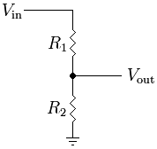
One very commonly used, but simple electrical circuit is the Voltage Divider, where two resistive values are connected between a known voltage and ground. The voltage measured between the resistors is a fraction of the supplied voltage in exact proportion to the value of the two resistors.
This has many uses, some common examples are to reduce a supplied voltage to a lower one, for example to bring it within the range measurable by an ADC, or if used with a known voltage and one known resistor it can be used to determine the other unknown resistance.
The equation
Examples
Example 1 - Battery Voltage
In this example Vin is an unknown value, the current battery voltage, but our microcontroller is powered from a linear regulator that supplies a fixed 5V from the battery source which is somewhere between 6v and 12v.
For this we would be unable to sample the voltage directly as it is higher than the supply voltage to the ADC, by using two resistors we can divide the battery voltage down so that it is within the range of the ADC.
Suggestions, select R1 as 20K, and R2 as 10K. The voltage at Vout will be one third of the battery voltage, which will be within the range of the ADC. Simple math will then provide the actual voltage figure.
Example 2 - Light Dependant Resistor
In this example Vin is a known 5v the same as the ADC power supply, but R1 is a sensor with a resistance in the 5-20K ohm range. In order to measure this resistance we use a fixed value for R2, eg 10K. We can now determine that the current value of R1 is by measuring Vout and plugging the known values into the formula to get.