Activities
Sensing the World - Analogue Values
This workshop is predominantly about how to read analogue input voltages.
The page refers heavily to the Data Sheet for the PIC16F1455.
PIC16F1455 Chapter 16.0 Analog-to-Digital Convertor (ADC) Module
Setup
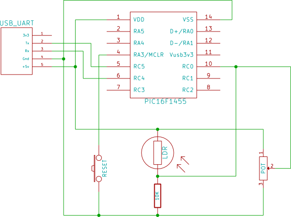
Components:
- PIC16F1455
- USB Uart
- Reset button (optional)
- Thermistor / LDR / Potentiometer
- 10K Resistor
You should connect only one of the following as per the diagram :-
- Potentiometer
- LDR + 10K resistor
- Thermistor + 10K resistor
Basic Theory
Many analogue sensors (eg Thermistor, and Light Dependant Resistor (LDR)) vary their resistance in response to the external stimulus, we can convert that to a varying voltage through the use of a Voltage Divider circuit.
Port configuration
Setup a new MPLab project as previous examples and setup the serial port so that you can view the results.
Now, according to section 16.2.6 (page 159) we need the following steps
- Set pin RC0 to analog mode (ANSELC) and set as an input (TRISC)
- Select a suitable ADC Clock from Table 16-1 according to the CPU speed and set ADCS in ADCON1 accordingly
- Select Vcc as the reference voltage ADPREF = 0b00 in ADCON1
- Set the input selector to RC0/AN4 (Table 2, page 8) by setting ADCON0.CHS = 0b00100
- Right justify the result by setting ADFM in ADCON1
- Enable the ADC module by setting ADON in ADCON0
- Wait for at least the ADC clock interval defined in table 16-1.1
Reading the result
Now you can read the value, set the GO bit of ADCON0, wait for the bit to clear, then read the result from ADRESH, ADRESL.
Displaying the result
Write the results to the serial port so that you can see the values.
If your serial code has a putch function then use printf to display a formatted value, otherwise convert the value to hex. eg.
const char hextable[] = "0123456789ABCDEF";

void printhex(uint8_t val)
{
    putch( hextable[ val>>4 ] );
    putch( hextable[ val & 0x0F ] );
}
Interpreting the results
If you had connected the potentiometer then the value you have read is the range 0-1023 giving the position of the potentiometer. If you only want an 8-bit value (0-255) then set ADFM to left justify the result and read only ADRESH.
If you have connected the thermistor or LDR then you can use the formulas on the Voltage Divider page to calculate the resistance value, if you have a datasheet it will likely give you another formula to convert that value to a temperature or brightness value. Otherwise you will need to take two readings at known values, and determine your own calibration.
Further Practice
Measure supply voltage - If you enable the internal Fixed Voltage Reference (Chapter 14.0) and select it as the input to the ADC, with Vcc as the reference voltage, you can determine what Vcc is as you know that 1.024V = Vcc * (ADRES[HL] / 1024)