Activities
Building a Robot
Physical Assembly
Assemble the base plate, motors, and wheels
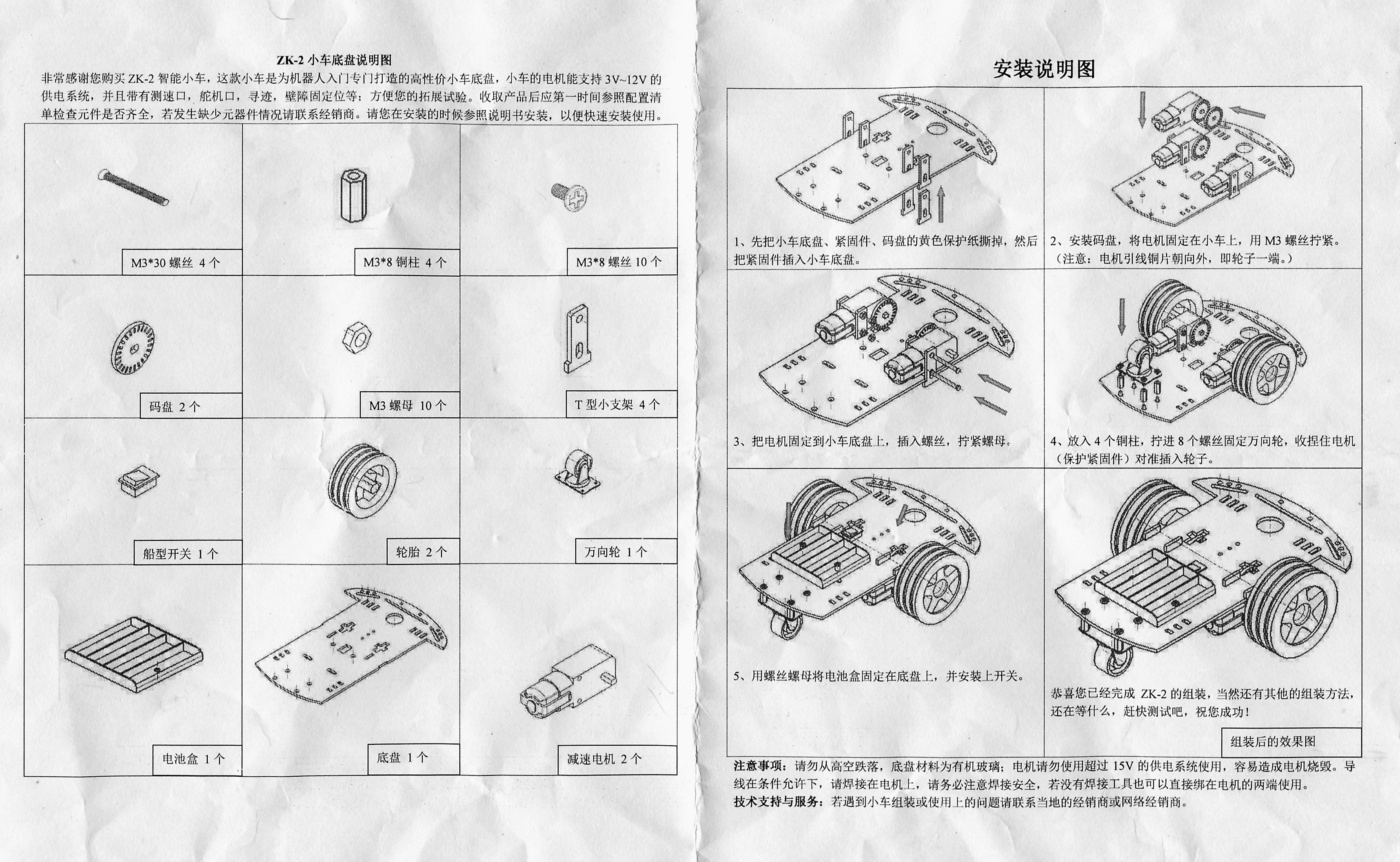
- Slide the encoder wheel onto the axel of the motors (Diagram 2) (optional)
- Slot the support brackets through the base plate (Diagram 1)
- Position the motor between the support brackets
- Ensure the solder connection points are accessible
- Push the 30mm M3 screws through the support leg, through the hole int he motor casing, then through the other support leg, secure with an M3 nut. (Diagram 3)
- Repeat for other motor
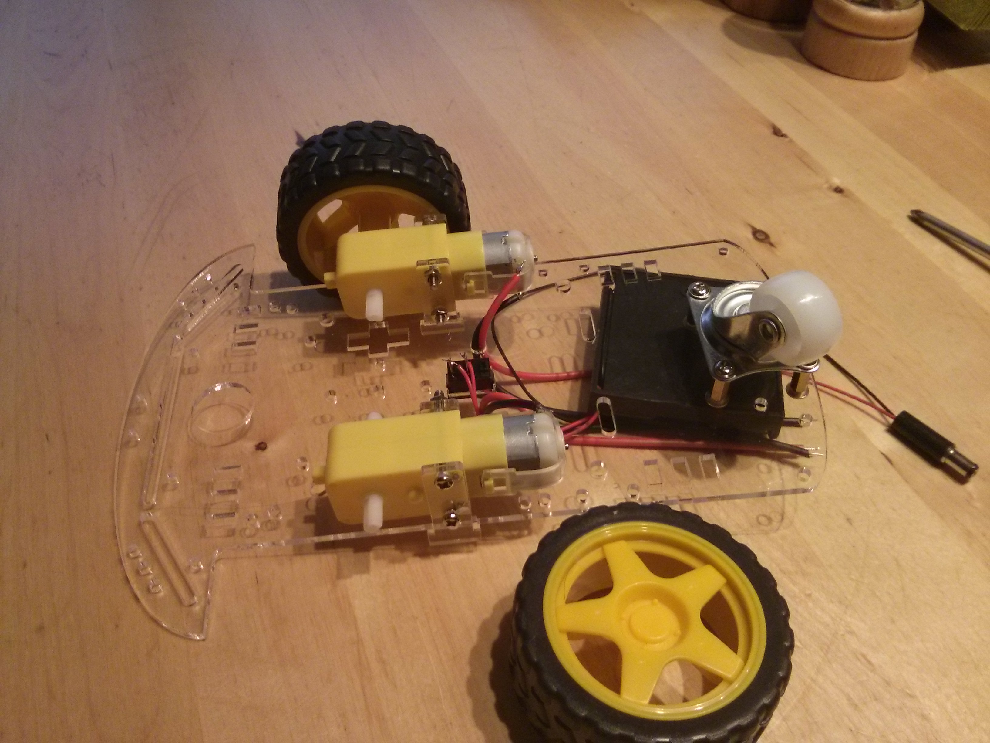
- Secure the 4x M3 8mm metal standoffs to the chassis using M3 8mm screws
- Attach the caster wheel to the standoffs using M3 8mm screws (Diagram 4)
- Attach the Battery box to the chassis using 2x M3 8mm countersunk screws + nuts
- Clip the switch into the hole just infront of the battery box.
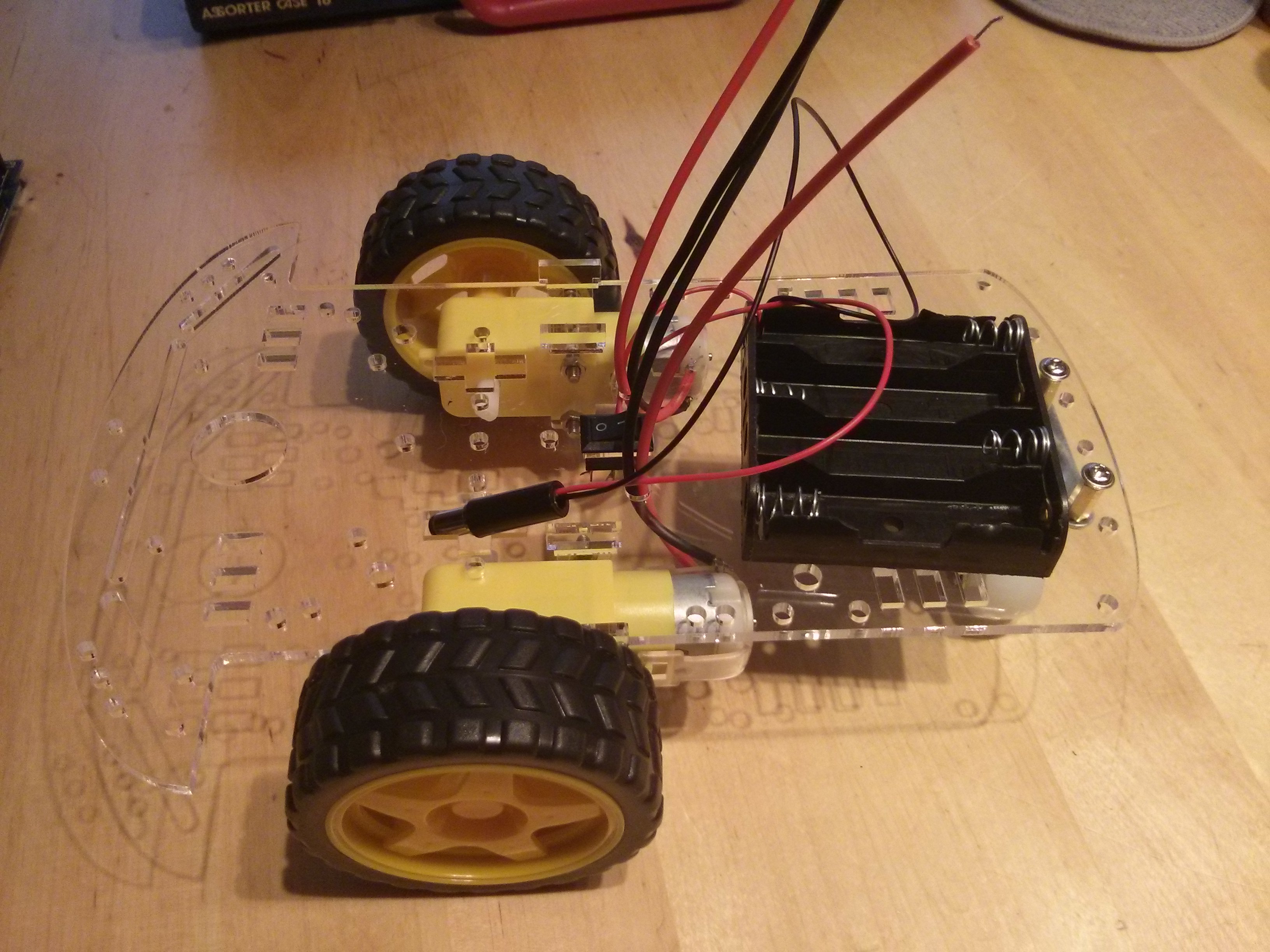
- Using the thicker wires solder one red and one black wire to each motor, run the wires through holes in the chassis plate to the top side
- Pass the wires from the battery box down through the chassis plate to one side of the switch.
- cut the red wire so that you have just enough to reach from the battery box to the switch, solder the cut ends to the switch.
- Solder the remains of the red wire to the other connector of the switch
- Pass the red and black battery wires back up through the chassis on the other side of the switch
- solder the 2.1mm DC Barrel connector to the red and black wires from the switch, red to the centre pin
- push the wheels onto the motors
- Last change March 21, 2016, at 05:02 PM
- Registered in England and Wales 08777436


