Activities
A gentle introduction to the Arduino
Requirements
For this tutorial you will need the following items :-
- A Laptop, with the Arduino Environment installed
- An Arduino Uno and its USB cable
- One LED, any colour, and a 220ohm resistor
- One push button
- One LDR (Light Dependant Resistor) and a resistor, 1kohm will do
- One piezo sounder or 8ohm speaker
- One Servo e.g. SG90 micro servo
- Some interconnect wires and perhaps a breadboard
- Optional for last example: NeoPixels or other WS2812 LEDs
Setting up the environment
Plug in your Uno board, make sure the lights come on, then launch the Arduino software. From the tools menu, set the Board type to Arduino Uno
First Sketch: Blink
For the first sketch, or program, we will load one of the examples that ships with the arduino environment.
From the menus, select File -> Examples -> 01 Basics -> Blink
This will load the example program which blinks the onboard LED that is connected to pin 13
Press the tick icon to 'Verify' (compile) the program, and if that has no errors press the arrow icon to upload the software to your arduino. If all went correctly then the program will run immediately after the upload has completed.
You should see one of the onboard LEDs flashing on and off slowly.
Anatomy of a 'sketch'
Programs for the arduino are written in the C++ (you may also use plain C) programming language. There must always be two specific functions, these are 'setup' which is run once when the device powers up or resets, and 'loop' which runs over and over again forever.
In the 'Blink' example, the setup function has one task, and that is to set pin 13 to be a digital (on/off) output.
The loop function then turns the output on, pauses, turns the output off, pauses again, then repeats.
You can satisfy yourself that it is your function that is running on the arduino by modifying these instructions to flash the LED in a different pattern or speed.
Sketch Two: Fade
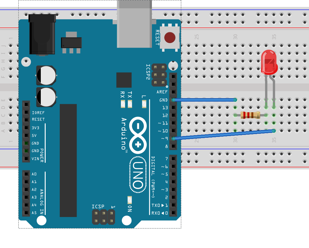
For this program we are going to fade an LED on and off instead of blinking it, however this requires one of the output pins that is labelled as supporting PWM mode, which does not include pin 13, so we have to wire our own LED to a different pin. For example, pin 9
- Load the example sketch '01 Basics' -> 'Fade'
- Connect the Long wire of your LED to pin 9
- Connect the short wire to the resistor
- Connect the other side of the resistor to Gnd
- Verify and Upload the sketch
You should now see your LED fade on and off.
This sketch worked by using the AnalogWrite function to output a PWM signal that varies the LEDs brightness.
Sketch Three: Button
This sketch demonstrates a very simple use of a push button.
- Load the example sketch '02 Digital' -> 'Button'
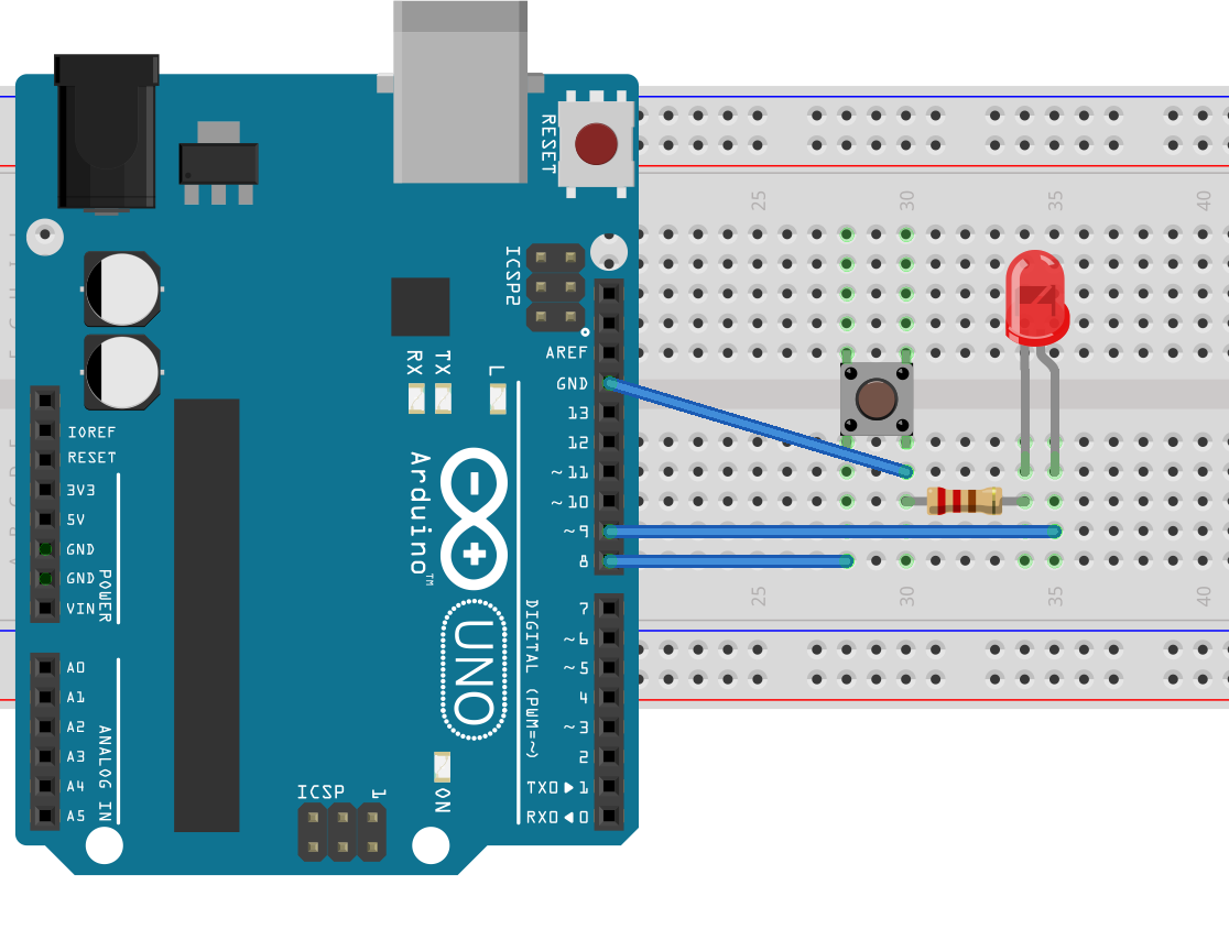
- Connect your button between pin 8 and Gnd
- Edit the sketch, change ledPin to 9
- change buttonPin to 8
- change the pinMode reference to 'INPUT' to instead say 'INPUT_PULLUP'
- Verify and Upload the sketch
- Press the button
By setting the pinMode to INPUT_PULLUP we are telling the chip to connect a resistor between the pin and the 5v power rail, this has the effect of gently pulling the line to a definite on/1 state, instead of leaving it floating at an arbitrary level. When you press your button, the pin gets connected directly to the Gnd line, which overpowers the resistor and pulls the line down to an off/0 state. The software reads this on/off state and changes the output to the LED accordingly.
Sketch Four: Serial Port
This example will demonstrate how you can have the arduino send messages through its serial port back to your laptop, this allows you to receive more detailed information from your sketch, to output debugging messages, or even to write a user interface.
- Load the example sketch '01 Basics' -> 'DigitalReadSerial'
- change pushButton to 8
- change the pinMode to INPUT_PULLUP as in sketch three
- Verify and Upload the sketch
- Select Tools -> Serial Monitor
- Ensure the 'baud rate' selection is 9600
- Press the button, watch the values in the monitor change
This sketch runs a continuous loop of testing the value of the input pin, and then printing the value to the serial port for you to see. As pressing the button changes the state of the input pin, so does the printed message change.
Sketch Five: Analogue Inputs
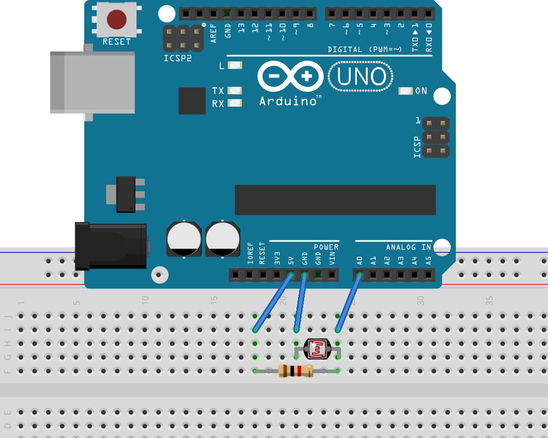
This example will build upon the previous ones to show how you can read more than just on/off states, in this case we will be reading a voltage that varies due to the changing resistance of a Light Dependant Resistor placed in a Voltage Divider configuration.
- Load the example sketch '03 Analog' -> 'AnalogInOutSerial'
- Connect the LDR between the 5v and A0 pins
- Connect the resistor between the A0 and Gnd pins
- Verify and Upload your sketch
- Select the Serial Monitor
The serial monitor now shows the a value between 0 and 1023, which represents a voltage on the input pin between 0 and 5 volts. When you cover the LDR or expose it to light, the value will change. The exact range of values it will show depends upon the resistance range of the LDR and the chosen resistor value.
You can expand on this example by replacing the LDR with a Thermistor to measure temperature.
Sketch Six: Make a Noise
This example demonstrates how to output a signal that when connected to a speaker makes a noise, you can use this to make alarm noises, user feedback beeps, or even play a tune.
- Load the example sketch '02 Digital - ToneMelody'
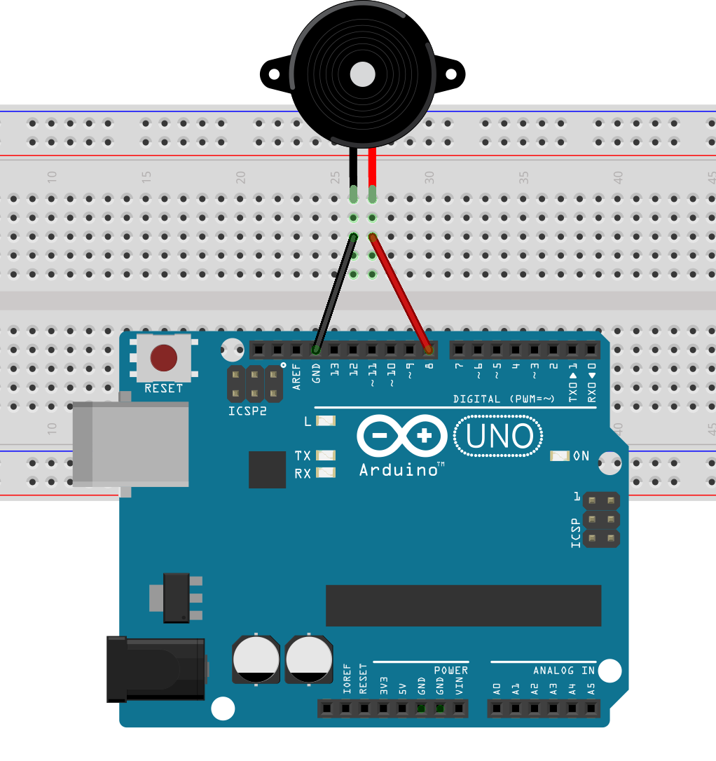
- Connect the pieze sounder between Gnd and pin 8
- Verify and Upload your sketch
Experiment writing your own tunes.
Sketch Seven: Make it Move
This example shows one way to have your Arduino make something physically move, we will use a servo for this example, these devices rotate to a position within a 180 degree arc based upon a signal from a controller. These are used extensively in remote control toys, but you can use them for many other things, e.g. making an old style analogue pointer dial, or indicator, by printing and attaching a pointing arm to the servo.
- Load the example sketch 'Servo - Sweep'
- If you can't find this in the menu, you may need to install the Servo library via Sketch -> Include Library -> Manage Libraries...
- Connect the Brown wire to Gnd
- Connect the Red wire to 5v
- Connect the Yellow wire to pin 9
- Verify and Upload your sketch
This example simply loops from 0 to 180 and back again, updating the servo position with each step.
For an interesting alternative, mix this example with the LDR reading from sketch 5, and have the position of the servo shift in response to brightness.
Sketch Eight (Optional): Rainbow Colours
The NeoPixel / WS2812 LED devices are a small package containing red, green, and blue LEDs along with a controller chip. That chip can be sent a digital signal which represents the 8-bit (0-255) values of brightness that it should display on its LEDs. This allows you to set each package to one of 16 million colours. These devices are also connected together in a chain, such that when you send a 25th bit to the first chip, it will output the 1st bit it was sent, and shuffle all of the values along, such that you can use a single data line to transmit different values to each light in pretty much any length of chain.
The complexities of transmitting the very precisely timed messages that the LEDs require is handled by the Adafruit NeoPixel library, and our software only needs to concern itself with which colours should be displayed at any given time.
- Install the NeoPixel library which you can download from the Adafruit website
- Load the example sketch 'Adafruit NeoPixels' -> 'strandtest'
- On line 12 change the call to Adafruit_NeoPixel() to match the length and type of strip you have
- In setup(), after begin() add the line: strip.setBrightness(32);
- Verify and upload
- Relax and watch the pretty lights
The setBrightness call is necessary because these lights can be extremely bright, and at full brightness they can also draw a lot of power from your Arduino, potentially overloading it, so setting it to a low value saves both your eyes and your board.
The WS2812 lights can be bought in many forms; rings, grids, and strips, from Adafruit themselves and many other sources. In the UK you will typically pay around £20 for a one metre strip with 60 WS2812 LEDs on it, but if you buy in bulk from China the price drops quite a lot.


