Activities
Isolation Milling with FlatCAM
Install and run FlatCAM for this stage.
Before doing anything else, select the Options tab, and under BOTH 'PROJECT OPTIONS' and 'APPLICATION DEFAULS' set Units: mm
I exported my PCB as 'tutorial' so i need to load the following files:-
- Open Gerber -> tutorial_copperBottom.gbl
- Open Gerber -> tutorial_contour.gm1
- Open Excellon -> tutorial_drill.txt
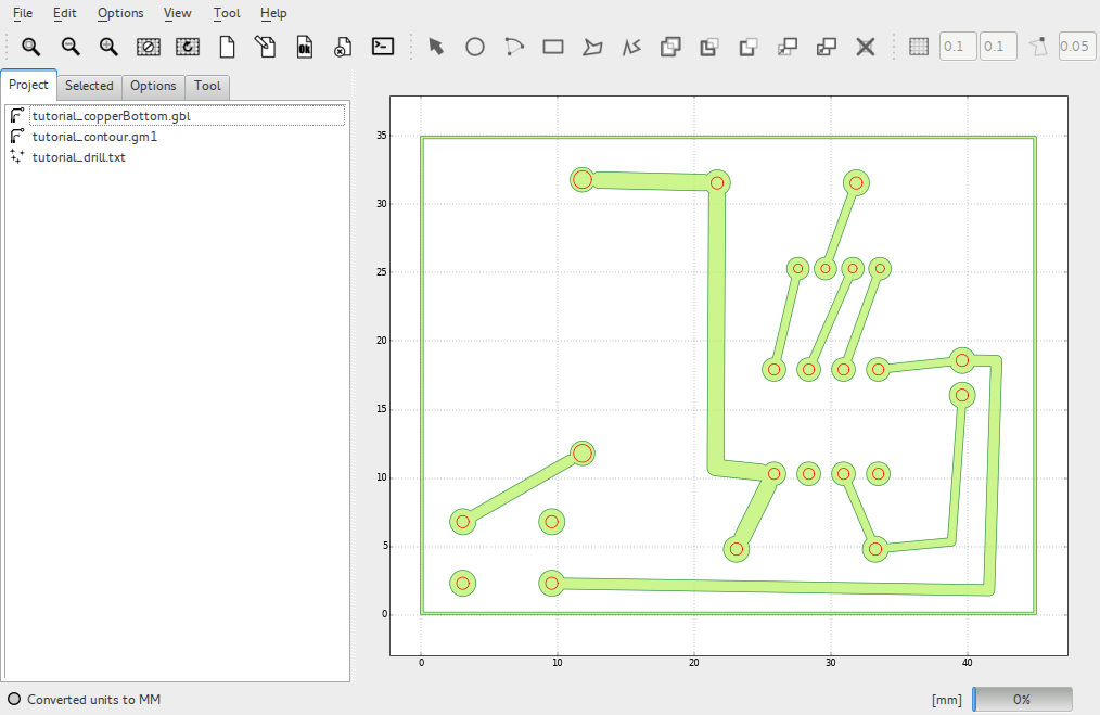
The 'Project' tab will now list three layers corresponding to the three files you loaded.
- one for the pcb tracks
- one for the board outline
- one for the drilling instructions (red circles)
The copper clad board we are cutting is 1.5mm thick.
When we setup the CNC machine, we move the tip of the tools to roughly 0.1mm away from the surface of the material, these values will affect some of our choices below.
For this excercise we are going to use three milling bits :-
- 0.1mm engraving bit (V shaped)
- 0.8mm end mill (we will use this to drill holes)
- 3.175mm end mill which we use to cut the outline
We will now go through the stages of turning these outlines into CNC instructions, in each case you select the layer to work with from the 'Project' tab, then you switch to the 'Selected' tab to see the options for it.
Routing the tracks
Highlight tutorial_copperBottom.gbl and press the 'Selected' tab.
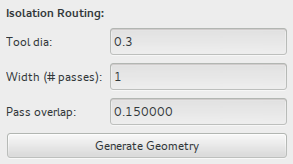
The engraving tool we use is 0.1mm at its tip, but varies with depth, so we will exaggerate this setting s far as we can without tracks becoming merged, a Tool dia: 0.3 seems to work well. With a Width/passes of '1'.
Now press the Generate Geometry button, this creates a new layer called tutorial_copperBottom.gbl_iso which holds this new outline.
Highlight the new tutorial_copperBottom.gbl_iso layer, and go to the Selected tab.
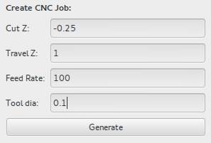
In the Create CNC Job section use the following settings:-
- Cut Z: -0.25
- Travel Z: 1
- Feed Rate: 100
- Tool dia: 0.1
Then hit the 'Generate' button to make a new layer ending in _cnc
Highlight the new tutorial_copperBottom.gbl_iso_cnc layer, and go to the selected tab.
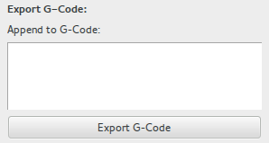
Press the Export G-Code button, this will ask you for a filename, the name is unimportant it is for your benefit. perhaps something like isolation.gcode
That completes this part.
Drilling the holes
Highlight the 'tutorial_drill.txt' layer and go to the Selected tab.
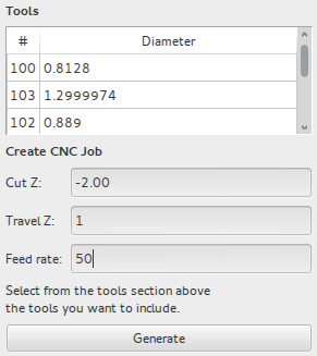
The 'Tools' box will list all of the different sizes of hole that your PCB design requires.
For this exercise we know that a single 0.8mm drill is suitable for all of the holes, so highlight ALL of the tools using Ctrl and clicking on all the numbers in the # column.
Also set the following values
- Cut Z: -2.00 (well through the board)
- Travel Z: 1.00 (mm above service)
- Feed rate: 50 (mm/min)
And press Generate, then select the new 'tutorial_drill.txt_cnc' layer and Export GCode as you did before.
Routing the board outline
Select the 'tutorial_contour.gm1' layer and go to the Selected tab.
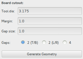
This time use the Board cutout: section.
- Tool dia: 3.175 (mm endmill)
- Margin: 1.0 (mm gap around the board)
- Gap size: 1.0 (mm size of tags joining board to frame)
- Gaps: 2 T/B (2 tabs, top and bottom)
And 'Generate Geometry'' to create a new layer with the board cutout paths.
Select the new 'tutorial_contour.gm1_cutout' layer, got to the Selected tab.
Create CNC Job:
- Cut Z: -2.0 (mm well through the PCB)
- Travel Z: 1.0 (mm above the surface)
- Feed rate: 100 (mm/min we can go quite fast with this tool)
- Tool dia: 3.175 (mm endmill)
Then 'Generate' to create the CNC layer, and as before select this and 'Export G-Code' to create a file.
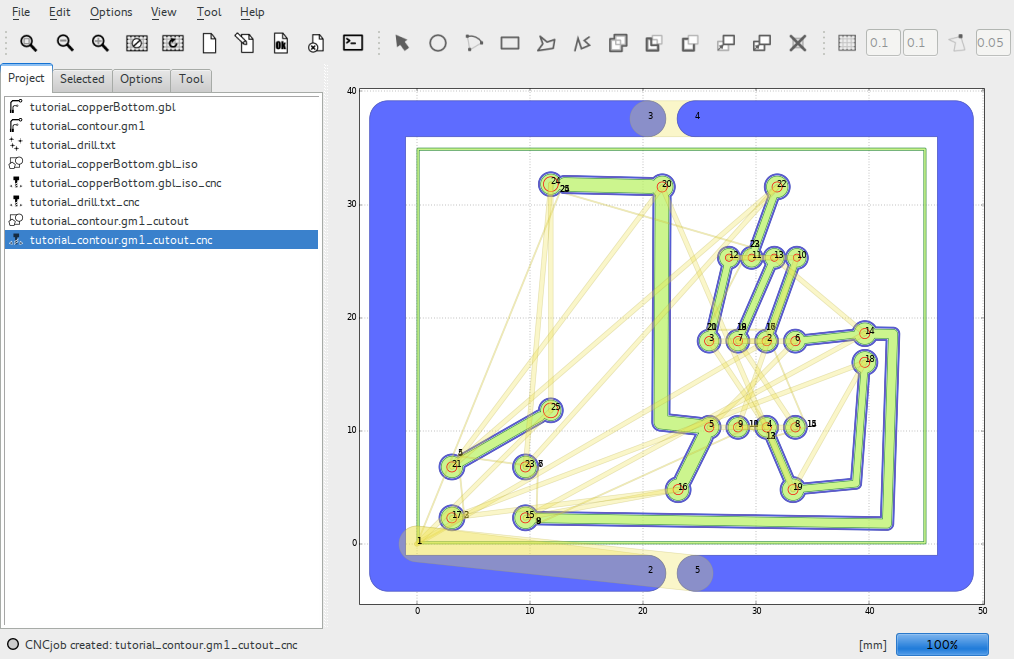
The finished screen should look something like this :-
You should now have three gcode files, e.g.
- isolation.gcode
- drill.gcode
- cutout.gcode
Next Stage: Controlling the Mill

