Activities
Building a Robot
Motors

Assemble the Control boards and wire motors
- Locate the large rectangular Controller mounting plate
- Screw 6x 5mm nylon standoffs onto the plate using nuts to secure them
- Mount 4x 25mm metal standoffs onto the chassis plate, around the battery box at the corners of the controller plate.
- secure the controller plate to the 25mm standoffs using 4x 6mm pan head screws
- Mount the arduino uno to the nylon standoffs using 4x 4mm pan head screws
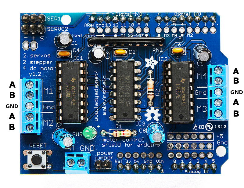
- Solder pin headers into the three rows of holes adjacent to the 'analog in' pins of the L293D motor shield
- Push the motor control shield into place atop the of the uno
- connect the thick red and black wires from the motors to the M1 & M2 screw terminals of the motor control shield
Theory
Fleming's Left Hand rule.

A current flowing through a wire generates a magnetic field, when acted upon by another magnetic field produces a force which moves the wire.
Thus a simple motor can be created using a coil of wire, a battery, and a permanent magnet.
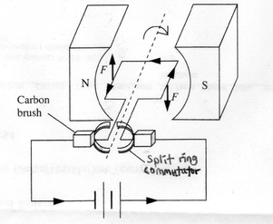
This gives us the standard d.c. motor, that continuously spins in one direction when a direct current is applied, and in the opposite direction when the polarity is reversed.
Finer control
When more fine grained movements are required, and when you really need to know exactly how far around the motor has turned, you can use a stepper motor.
These motors consist of a number of separate coils, when one coil is powered it causes the motor to turn a single step towards it, it is then necessary to powered the next coil in sequence to take a further step. this way the exact amount of rotation is always known, and it is possible to halt and hold the rotation at any given step by keeping the coil powered.
Powering such a motor is a lot more complex than a dc motor, but all of the hard work is taken away by the many kinds of driver chips and boards that are available. e.g. the Pololu StepStick
Stepper motors are available in many sizes and step counts, a common size that is used in 3d printer construction is the NEMA 17 size, 200 steps per rotation motors, these can be obtain for around £10 each and are quire powerful.
Our robot
Whilst stepper motors give wonderful amounts f control, they are larger, heavier, and a lot more expensive than dc motors. Our robot design uses simple dc motors with a gearbox which slows their rotation down to more managable speeds.
Supplied with your kit is the L293D Motor Shield this contains chips which can drive 2 stepper motors, or upto 4 dc motors, as well as providing connections for Servos and other sensors. There is a list of helpful tips and lists of used and unused pins in the Motor Shield FAQ
Controlling the Motors
Adafruit provide a library which simplifies many of the functions of this Motor Control shield. Please download and install it into your Arduino environment.
Ignore their instructions on how to install it, just download the .ZIP file and from the Arduino software select: Sketch -> Include Library -> Add .ZIP Library and select the file.
Now load File -> Examples -> Adafruit Motor Shield library -> Motor Test
This tests Motor 4 (the M4 screw terminals), change the motor(4) number to the motor you wish to test.
Bonus
For extra speed, or if your motors are sluggish, solder some extra red & black wire to the dc barrel jack, and connect the other end to the two-screw-terminal power connector (pictured at the bottom of the above photo) on the motor driver board. Don't forget to remove the PWR jumper next to it!